|
|
|
|
|
Discussion
Sebart Sukhoi 2.2m Airworthy?
Hi guys,
I'm almost done "assembling" a Sebart Sukhoi 2.2m and as I don't have anyone to give the bird a once over before I fly it I was hoping I could take advantage of all you experienced modelers to help ensure I haven't done anything stupid  . .This is my first gasser, my first aerobatic aircraft and my first model bigger than .40 glow so I'm a little apprehensive  . . I have to say, I really expected a lot less time input and effort in "assembling" an ARF aerobatic aircraft but it's actually taken me a fair bit of time and effort all in all. I'll post a few pics of what I've done so far and ask that if anyone sees anything they consider risky, stupid or dangerous they let me know  . Having said that a little positive reinforcement is always appreciated . Having said that a little positive reinforcement is always appreciated  . In addition, if anyone has experience with this plane and can make some suggestions / give some tips I'm all ears! . In addition, if anyone has experience with this plane and can make some suggestions / give some tips I'm all ears! Aside from this first post which is already an essay I'll try to keep it brief. I'll start posting some pics etc shortly. Cheers, Dom |
|
|
|
|
|
|
|
Ok, started with the fuse. Wicked thin Zap into all joints.
The fuse was going to be too long to fit into my Renault Hatch so I had to make a removable rudder. I replaced all of the kit supplied hinges with Robart Hinges, drilled out the steel hinge points and ran a 2-56 rod through the four rudder hinges that is removable from the bottom of the rudder. This 2-56 rod has a 90degree bend at the bottom that provides something to grip whilst inserting / removing the rod and provides a method to secure the rod by clipping it into a plastic control rod clevis that I attached to the tailwheel bracket. The Rudder pull-pull cables are secured to the control horns via Secraft clevises with a pin and clip arrangement that allow for quick and easy removal / installation. I used 5 min epoxy to glue in all the hinges on this model. Figured CA wasn't going to cut it. |
|
|
|
|
|
While we are at the back-end of the fuse, I used 1 inch SWB servo arms for the elevators. The control horns on the elevators are 1.5". I read somewhere that it is better to have equal size arms / horns but I mainly intend on doing IMAC style flying at the moment and figured I didn't want too much throw, but rather, slightly better resolution?
I'm using Futaba 9157 servos all round. Using the 1" arms I still get more than enough throw I think (haven't set up radio / throws yet). Any suggestions on required elevator throw for IMAC style flying? Sebart manual recommends 20deg low rates, 50deg high. Sounds like a lot. Photo shows max throw with these servo arms (could get a bit more by enlarging the holes in the elevators as the arms currently bottom out on the elevator skins). Oh, also, the kit comes with 3mm metric ball links. I replaced these with Dubro 4-40 links but used the 3mm bolt which provides a tighter fit with less slop than the 4-40 bolts. |
|
|
|
|
|
I went with a DLE55 and MTW RE2 pipe for this plane.
The Sebart Sukhoi comes with a pipe tunnel already built in but it isn't long enough. I had to extend the pipe tunnel by another 8 inches or so to make it fit and built a box with 3mm quarter grain balsa. I used the last former of the original pipe tunnel as a pipe holder, cutting out a slightly oversize hole and using MTW silicon tubing to provide a tight fit. There is only about 2mm gap betwen the wood former and the pipe wall; is this enough? I decided to make a cover for the pipe tunnel out of thin (1/80th) G10 as I didn't like the though of what the totally exposed pipe tunnel and formers would do to the aerodynamics of the plane. I cut holes in the cover to provide (hopefully) sufficient cooling. I will paint the pipe cover to match the rest of the plane. |
|
|
|
|
|
Moving to the front of the plane now, I decided that I would beef up the engine box and firewall a little. I did this because I knew I would need weight at the front of the plane to balance the long pipe and also for peace of mind. I also assumed I would be mounting batteries to the engine box to get the right CoG as well so figured a bit of extra strength wouldn't hurt.
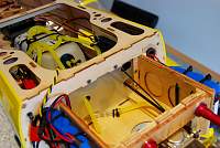
I doubled up the engine box sides with 4mm lite ply and some triangular stock. I also dowel pinned the firewall to the side plates using 4mm dowel and epoxy. Further, I glued 4mm aircraft ply to the firewall to both stiffen the firewall and move the engine out a little further to clear the cowl. I then fuel-proofed the whole box, inside and out, with west systems epoxy, and also ran the epoxy right up under the fuel tank location as well. I did mount both 2600mAh receiver batteries and 1400mAh ignition battery to the sides of the engine box using cable ties and foam between the batteries and box to damped some of the high frequency vibration and I mounted the ignition on top. Hopefully no issues with RF interference etc...  The engine is mounted with the 4 degrees of right thrust built into the engine box with no modification. |
|
|
|
|
|
As you can see in the pics, I decided to use a carbon pushrod for the throttle and I also installed a choke servo as I couldn't figure out a simple way to route a manual choke pushrod.
The carbon throttle pushrod is a carbon tube with 4-40 rods epoxied in about 2inches on either side. 4-40 ball links to both the servo and engine throttle arm. There is no slop in the linkage and so I don't think there will be any metal on metal contact issues... The choke linkage is a steel rod with a plastic clevis to the choke arm. This linkage is what was supplied in the kit as the throttle linkage. Using a Hitec 5685MH servo for the throttle and Futaba s3001 for the choke. I must say, all of the Futaba servos are super quiet and don't chatter at all, whilst the Hitec sounds like its crackling and hissing almost all the time. The servo sounds like its got a short and is about to set itself on fire  . .I made a shield / screen out of G10 behind the engine box in the fuse to minimise the amount of fuel spitting out of the carby getting into the rest of the fuse. |
|
|
|
|
|
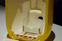
In order to ensure good engine cooling I've put some baffling in the cowl to help direct airflow over the cylinder head. I'm also hoping that this will drive air into the pipe tunnel to help cool the tuned pipe.
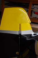
I'm not going to cut an exit hole in the bottom of the cowl as directed in the instruction as I'm hoping that this will force more airflow into the pipe tunnel and result in better overall cooling of the engine / pipe system... ??? In the pics you can also see that I've added additional mounting brackets? for the canopy, which I've read tends to be a weak point of the Sebart design. |
|
|
|
|
|
Just a suggestion but i would be a little concerned about the zip ties on those batteries, especially the way they are run in between the cells. I would use some velcro straps on the batteries and ignition. Just my .02 cents
|
|
|
|
|
USA, OH, Aurora
Joined Jan 2006
30,070 Posts
|
Also on the elevator servos, I'd move the linkage to the inside hole of the elevator horn. You want as close to the same amount of leverage on both sides. This will give you a much better resolution.
The reason Imac guys use short 1" servo arms is because they run short control horns keeping the ratio as close to 1:1, which in turn gives them full resolution to be as smooth as possible. The way you have it now, you will get decent throw, but it will not be an even throw.. By moving the ele horn to the inside hole, it will help you a bit. |
|
|
|
|
|
Also i would remove the zip tie on the braided spark plug wire.
|
|
|
||
|
|
Thanks Wayne, thanks Sleepy
 I'll change the zip ties to something with a bit more surface area. Quote:
Is it better to just have the braided ignition wire hanging free? |
|
|
|
|
|
USA, OH, Aurora
Joined Jan 2006
30,070 Posts
|
The highest torque is obtained when you use the hole nearest to the center on the servo side, but farthest from the surface on the aileron side. What you gain in torque, you'll lose in travel distance, so consider how much total travel you'll need when you setup your system.
|
|
|
||
|
|
Quote:
 . So I might actually have to go one hole further down on the servo arm for IMAC throws. . So I might actually have to go one hole further down on the servo arm for IMAC throws.
|
|
|
|
|
|
|
I don't have much clearance between the prop and the cowling. Is this enough or can the prop flex enough to make contact with the cowl?
|
|
|
|
|
|
I used a 2.5inch SWB straight servo arm and Secraft wire fittings for the rudder. Crossed wires. I also strengthed the rudder servo tray as I noticed that the tray was flexing a lot and figured it couldn't be good for rudder precision.
For the fuel tank install I used a 24oz dubro tank, dubro gas stopper, alloy fuel cap, secraft fibre bubbleless clunk, secraft fuel dot and 1/8th Tygon tubing. I also put a filter between the t-piece from the fuel dot and carby. I put two loops through the overflow tubing as read somewhere else on this forum. I soldered barbs onto both sides of the tank copper tubing and also put cable ties on both ends. |
«
Previous Thread
|
Next Thread
»
| Currently Active Users Viewing This Thread: 1 (0 members and 1 guests) | |
| Thread Tools | |


