|
|
|
|
|
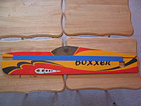
Team OMP Presents the Boxxer ARF!!!
Good morning Flying Giants!!!
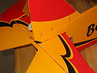
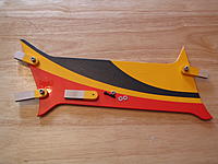
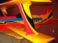
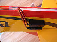
Well, by poupular demand, Team OMP is proud to announce the OMP Boxxer ARF!!! No, this is not a "maybe someday" project, these are a "DONE NOW" project. The airplanes are in stock now, and shipping to customers. Clean off your work space, find yourself your best 46 to 82 size glow engine (or electric equal), dig up 5 servos and a reciever! Here we go.......... Soon to appear at www.ohiomodelplanes.com . |
|
|
|
|
|
|
|
Re: Team OMP Presents the Boxxer ARF!!!
The first step involves the obvious time with the sealing iron. Smooth it up, and get set to move on. For my plane, the only part that was noticable loose was the diamonds under the lower wing.
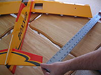
The first real work involves getting the plane ready to set the top wing incidence, if you do not have an incidence meter... If you do, skip this stuff... 1: To align the top wing without an incidence meter, you will need to create a centerline to work from. The engine mount is set to zero degrees of up and down thrust. The horizontal stab is set to zero degrees as well. To find this centerline, place a long measuring stick down one side of the fuselage, and create an approximate line from the bottom edge of the top motor mount stick to the top edge of the lower horizontal stab mount. You will need to put a piece of blue masking tape under the measuring stick, and over this line. 2: After the tape is in this GENERAL POSITION on the fuselage, again find the EXACT centerline from the motor mount to the horizontal stab. The exact position of this line begins at the top of the lower horizontal stab mount, and ends at a point 1/8 below the top motor mount stick. You can find this point, by placing a piece of scrap wood (1/8 thickness ply suggested) inside the motor mount area, or it is easy to “eyeball” the long measuring stick as parallel to the motor mount. 3: With minimal pressure, use a pen to draw this centerline on the tape exactly. Again, from 1/8 below the bottom edge of the top motor mount stick to the top edge of the lower horizontal stab mount. Note: Do not remove this blue tape until after the final gluing of the top wing has been completed and the epoxy has fully cured. |
|
|
|
|
|
Re: Team OMP Presents the Boxxer ARF!!!
Lower Wing Panel Install:
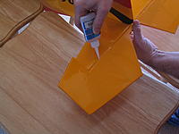
Note: The ailerons are added last, as aligning the top wing will be easier without ailerons to complicate the process. 1: Begin by adding a drop (or two) of thin CA to the wooden alignment dowels that are at the front and rear of the wing roots. Be sure they are glued in well, but just a drop is usually enough. After the CA is soaked in, give that area a shot of CA kicker (or allow a minute to fully cure), and move on to mounting the wing. 2: “Rough up” the two carbon fiber wing tubes with 150 to 220 grit sand paper, to give the glue a good contact surface for adhesion. 3: Next, install one panel onto the carbon fiber wing tubes. Slide the tubes into the wing root, and approximately 1/16 to 3/32 of an inch beyond the ply reinforcement on the second rib. Be sure you slide the tubes beyond their tapered portion. Use thin CA followed by medium CA to glue the tubes to both ply reinforcement plates. Allow thin CA to soak in a second or two, and then add the medium CA. After a few moments, apply CA kicker to the glue joints. |
|
|
|
|
|
Re: Team OMP Presents the Boxxer ARF!!!
Note: You can cover areas where epoxy is unwanted with blue masking tape to aid in keeping the plane clean during assembly.
4: The lower wing panels are glued to the fuselage with 30 minute epoxy. Apply epoxy to one wing root and to the corresponding exposed wood on the fuselage. Be sure to coat approximately ½ of an inch of each wing tube as well. Also, be sure there is epoxy on the forward and rear alignment dowels on the wing root. Slide the wing tubes through the fuselage, until the wing panel is in good contact with the fuselage and the alignment dowels are seated in their corresponding holes 5: Next, use rubbing alcohol and paper towels to clean up any epoxy that oozes out, before it cures. After confirming the wing panel is square to the fuselage, you can allow the epoxy to cure completely, or move on to the second panel immediately. If you epoxy both panels at the same time, you must work carefully, as to not allow the first panel to shift out of place, as you install the second. A second set of hands would make this work more smoothly. Gluing one panel, and allowing it to cure before moving on is recommended. 6: Before the epoxy has cured, use a right angle square to set the wing perpendicular to the fuselage. After the epoxy is cleaned up and the wing is set to square, use masking tape to hold the panel(s) in place as the epoxy cures. Check the panels for alignment every few minutes, as the epoxy cures. Also, check if any more epoxy is oozing out, and clean with rubbing alcohol and paper towels. |
|
|
||
|
|
Re: Team OMP Presents the Boxxer ARF!!!
Quote:
 Bob R. |
|
|
|
|
|
|
Re: Team OMP Presents the Boxxer ARF!!!
Horizontal Stab Install:
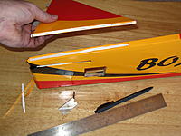
1: Center the horizontal stab in the slot at the rear of the fuselage. Measure that each outboard tip of the stab is equally distant from the fuselage first. Following that, you should measure from the outboard forward tip of the stab to the rearmost outboard tip on the adjacent wing. Measure several times, and then mark the stab, where it contacts the fuselage on top and bottom. 2: Remove the covering from the center of the stab, approximately 1/16 of an inch INSIDE the marks you made. It is best not to use a sharp knife, but a hot soldering iron, with a pointed tip. Use a metal straight edge as a guide, and slowly move the iron across the covering allowing heat, not pressure, to cut the covering. Simply cutting the covering with a sharp knife can often damage the stab, and almost guarantee a failure in flight during high “G” maneuvers 3: After removing covering from the top and bottom of the stab, prepare some 30 minute epoxy for bonding the stab to the fuselage. Some modelers prefer to use CA for this job, but the additional work time that epoxy allows will be of great benefit. Apply mixed epoxy to the top and bottom of the stab, on the exposed wood. Slip the stab in place (from the rear), and clean up any epoxy that oozes out with rubbing alcohol and paper towels. Realign the stab, measuring again stab tip to fuselage and stab tip to rear of bottom wing. Next, set the stab square to the fuselage, using a right angle, and tape the stab in place with masking tape. As with the wing, check the joint a few times, during the cure process. Measure to be sure the stab has not shifted, and clean whatever epoxy you can find with rubbing alcohol and paper towels. When fully cured (often longer than 30 minutes), remove the tape. |
|
|
|
|
|
Re: Team OMP Presents the Boxxer ARF!!!
Hinge the Elevator to the Stab:
1: To make this as easy as possible, the 4 hinge locations are pre slotted for you from the factory. Simply slide all hinges into place, checking from top and bottom that none of the hinges have missed the precut slots. After you are content that all hinges are centered in place, flex the elevator at the hinge, just beyond the amount of throw you intend to use for full 3D throws. Add thin CA to the top of the hinge, one drop at a time. Pause between drops for a second to allow the CA to wick into the wood. Five to six drops of CA per hinge is usually enough. Wait a few moments, and then repeat this process to the bottom of each hinge. Never use CA kicker on a hinge. If any CA runs over your covering, it can be removed with Acetone, or fingernail polish remover. Use either sparingly |
|
|
|
|
|
Re: Team OMP Presents the Boxxer ARF!!!
Vertical Fin Install:
1: The vertical fin is aligned by making sure there is a straight line along the rear of the fuselage to the rear of the vertical fin. This line is your rudder hinge line. The fin must be centered on the top of the fuselage. After aligning and centering, mark the location where the fin must be mounted. 2: Cut away covering from the top of the fuselage, approximately 1/16 of an inch inside the marks you made. Also, remove the covering from the bottom of the fin, to allow wood to wood contact. 3: The fin is “butt-glued” on top of the fuselage. Mix up a small amount of 30 minute epoxy and coat the exposed wood on top of the fuselage and the exposed wood on the bottom of the fin. Put the fin back in place, center, and align the fin. Use pins or masking tape to hold the fin in place as the glue cures. If using CA, run a bead of medium CA down the center of the wood you exposed on the fin and fuselage. After that, align, center, pin (or tape) and then apply a bead of medium CA around the fin. Allow the CA to soak for a few moments, then apply CA kicker. With either gluing technique, fin alignment must be absolutely correct, and the joint must be very strong. Again, 30 minute epoxy is most highly recommended for this procedure. |
|
|
|
|
|
Re: Team OMP Presents the Boxxer ARF!!!
Hinge the Fin to the Rudder:
1: Install the 4 pre slotted hinges for the fin and rudder in the same way you installed the elevator hinges. Do not forget to add the two hinges between the lower rudder and the lower fuselage. |
|
|
|
|
|
Re: Team OMP Presents the Boxxer ARF!!!
Strut to Lower Wing Initial Install: (No incidence meter required)
Note: If you happen to have an incidence meter, you can use it to set the top wing incidence, but these directions will aid those without such a tool. 1: Test fit the top wing by first assembling the mounting tabs to the struts with the supplied 4-40 x 5/8 bolts and locking nuts. The longer set of strut tabs are for the forward part of the struts. Fit the struts to the top wing (No Glue Yet) and then fit the top wing assembly to the lower wing/fuse assembly. 2: You can now confirm the top wing incidence by measuring from the leading edge and trailing edge of the top wing (at the center), down to the fuselage centerline you drew early in the assembly process. The measurement from the leading edge down to the centerline and from the trailing edge down to the centerline should be the same. Be certain that you are measuring from 90 degrees perpendicular to the centerline, straight up to the top wing leading and trailing edge. Do not remove the blue centerline tape until after the final gluing of the top wing has been completed and fully cured. |
|
|
|
|
|
Re: Team OMP Presents the Boxxer ARF!!!
Note: If the wing is not perpendicular to the fuselage, try flipping the mounting tabs around backwards until the top wing is perpendicular to the fuselage. You may also need to sand them on one side to allow the trailing edge to move forwards or backwards (on either side) in relation to the bottom wing.
3: Measure from the rear most tip of the wing to the rear most point on the fuselage on each side. The measurements should be the same for each side. Measure from the leading edge (at the tip) of the top wing to the leading edge of the bottom wing. These should be the same measurement for each side. Also measure from the trailing edge (at the tip) of the top wing to the trailing edge of the bottom wing. 4: Again, the critical measurements that must equal out to build a square biplane are: • From the middle of the wing leading edge and trailing edge down to perpendicular to the centerline. (Use a 90 degree square and a ruler.) • Wing trailing edge tip to rear fuselage for each side. • Top wing leading edge to bottom wing leading edge for each side. • Top wing trailing edge to bottom wing trailing edge for each side. 5: When you are satisfied with the wing alignment, tighten the bolts holding the strut to the tabs. By tightening the bolts at this point will allow you to remove the top wing and struts, with tabs attached, while keeping very close to the intended alignment. Carefully remove the upper wing and struts from the airplane. Use 30 minute epoxy to mount the strut tabs in the lower wing, with the strut still attached by bolts. (Make sure you put the bottom of the strut in the bottom wing.) Also slide the top wing onto the strut/tab assembly and into place to maintain alignment. Allow the epoxy to fully cure, and then you can remove the top wing, for the next few steps, if you like. |
|
|
|
|
|
Re: Team OMP Presents the Boxxer ARF!!!
Landing Gear Install:
1: Mount 2 1/2” foam wheels to the bottom of the aluminum landing gear using 6-32 x 1.25 bolts as axles, washers, and double locking nuts. You will likely have to drill out the plastic wheel hub to do this. Mount the completed landing gear to the fuselage with 10-32 x 1.25 bolts, washers, and locking nuts at the pre drilled location 2: Bend a right angle in the tail wheel assembly torque arm. Mount the tail wheel assembly to the rear of the fuselage with supplied wood screws. You can attach the torque arm to the rudder with a second 90 degree bend and a drilled hole. |
|
|
|
|
|
Re: Team OMP Presents the Boxxer ARF!!!
Radio Gear Install:
1: Begin by installing the tail servos. You will need two 12 to18 inch extensions. The length depends on the stock lead length of the servo. Install the extension on each servo by carefully removing the plastic connector housing. Plug each individual connector from the servo into the extension (matching colors carefully), and secure with small heat shrink tubing. This method is smaller, lighter, and more secure than simply plugging the plastic connectors together. 2: Install the top servo first by simply drilling the holes for the servo screws and slide in the servo. Next, install the bottom servo and pull both servo wires to the channel and push them in place in the channel in the bottom of the fuse. Cover over this channel with the supplied matching covering. (Clear tape used for photo.) A one inch wide strip approximately 24” long does a good job. Cut a small 1/8” x 5/16” hole in the bottom of the wing sheeting on the left wing immediately by the fuse and slide the wires in. Seal this hole and the ends of the servo extension wire tunnels with clear silicone. |
|
|
|
|
|
Re: Team OMP Presents the Boxxer ARF!!!
3: Mount the throttle servo to the right side fuselage on two ¼ inch ply/balsa triangle servo mounts. Determine the proper location based on the engine you choose and remove a small amount of covering to make a good wood to wood contact point. After gluing the mounts, you should fuel proof them with thin CA (allowed to soak in a bit) or epoxy. After the fuel proofing glue has cured, install the servo on the mount with rubber grommets (supplied with radio gear) to protect it from vibration. Cut a small hole in the lower wing sheeting and thread the servo wire through. Do not yet seal this hole, as you may use the same hole, to run aileron extensions, if you have chosen to use the top wing aileron servo option.
4: The main radio switch can be mounted anywhere, but the ideal place is on the left side, near the radio hatch. You can also mount the receiver wrapped in foam under this hatch. |
|
|
|
|
|
Re: Team OMP Presents the Boxxer ARF!!!
5: Next, add the aileron servo mounting tabs to the aileron servo hatches. First, pre-drill the servo mount tabs for the servo and mount the servo to the tabs, using the rubber grommets included with the radio gear. With the servo arm on the servo, find a location that best allows the servo arm to move freely. Use medium CA to glue the servo tabs to the hatches, and allow them to cure for a few moments, before using CA kicker. Wipe away the kicker residue with a paper towel or tissue, and add a second bead of medium CA to the outside of each mount tab, as a precaution, then use the CA kicker again.
6: Carefully cut away the covering material around the hatches you intend to use for the aileron servo locations. Again, if you are using the top wing locations, the supplied hatches will fit, but you will need to remove the dark covering that makes up the diamonds, from the hatch. You can clean up any covering adhesive residue with a small amount of Acetone or fingernail polish. Use your warm iron to adhere the cut covering inside the hatch openings. 7: The hatch covers are pre-drilled for hatch screws, but the backing plate (inside the wing) may not be. Using a small drill bit (5/64 recommended), and the hatch cover for alignment, to carefully drill the backing plate. Test fit the hatch and screws, and then remove both. Add one drop of thin CA to each hole you drilled, and use a “puff” of breath to clear CA from the open hole, before you allow it to cure. After the CA is fully cured, run the screws back in, and remove them a second time. |
«
Previous Thread
|
Next Thread
»
| Currently Active Users Viewing This Thread: 1 (0 members and 1 guests) | |
| Thread Tools | |
 Similar Threads
|
|||||
| Category | Thread | Thread Starter | Forum | Replies | Last Post |
| OMP 65" Yak Arf | JeeUm | Profile Planes | 37 | 04-23-2010 03:45 PM | |
| FG Rowing Crew/Boat Race team Victorious! | SleepyC | Chit Chat | 22 | 02-14-2007 10:33 AM | |
| 52" OMP Fusion X3D is Awesome | Jack Skip | Profile Planes | 4 | 12-09-2006 11:49 AM | |
| $100 off JTEC Radiowave 40% Extra 330 ARF & 35% Panzl ARF | Kevin Y | What's Hot | 14 | 10-24-2006 12:27 PM | |
| OMP Yak ARF VS. the water cannon. | JeeUm | Profile Planes | 21 | 04-14-2006 10:47 AM | |


