|
|
|
|
|
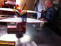
Finish setting the canopy base to zero degrees.
Next setting the wings to 0.80 degrees positive. |
|
|
|
|
|
|
|
Stab Adjustment to zero degrees
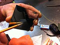
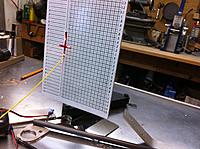
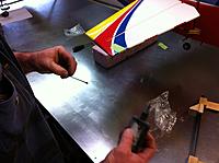
The Mirror Sensor Attachment set 6ft from laser unit. Blue locktite placed on the bottom stab set screw. The first reading is not clear sorry. Turned set screws to get to final reading of zero degrees Locked set screws while checking readings. Done Next check stab and rudder alignment. |
|
|
|
|
|
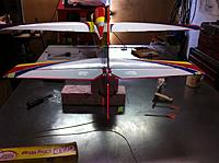
Checking Stab and Rudder Alignment.
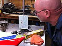
The laser vertical beam is focused on the rudder. Then the laser is moved so that the horizontal beam is focused on the two stabs. The alignment looks good. Same thing for the wings. Done |
|
|
|
|
|
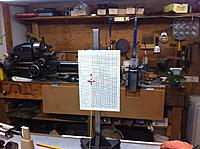
More info on Ray's laser incidence meter.
The right side of the beam measurement table is used for motor adjustments. He also gave me a copy of the MAC drawing he made for the Vanquish. |
|
|
|
|
Spring, Texas,USA
Joined Jul 2007
34 Posts
|
I am very happy with Extreme Flight, especially their rewards program.
Last year I competed in Intermediate and with some successes I gained $350 off my next purchase. I have just received my 2nd Vanquish, costing me just $300 +$125 shipping. I think it is wonderful that Extreme Flight are looking after their customers like this. They have entered the market of expensive composite planes with a competitive plane at a sensible price. I'm not sure if they are continuing to offer the Rewards Program this year. Nick Marson |
|
|
|
|
Spring, Texas,USA
Joined Jul 2007
34 Posts
|
Paul,
I could have sworn that I answered your post. I will add whatever I can, but no one can compete with your through assembly posts....excellent. The first thing I will do again is to replace the supplied hinges for Robart's. Robart's have steel pins, as opposed to aluminum, and are a better fit from the get-go. I noted some slop in the supplied ones. A magnet will prove the steel/ aluminum statement. Nick Marson |
|
|
|
|
Spring, Texas,USA
Joined Jul 2007
34 Posts
|
Robart Hinge Instalation
Having decided to install Robart's, I then decided to improve the mounting holes.
Most, with the exception of two, were accurately drilled. Idecided to remove a little extra at the hole entrance to accommodate the hingemechanism itself. The original holesgave the appearance that the hinge had just been jammed in to make room! The jig was inserted into each hole. This acted as a guide to cut 2 slots with an Exacto blade, perpendicular to the control surface. Nick Marson |
|
|
|
|
Spring, Texas,USA
Joined Jul 2007
34 Posts
|
Installing the Rudder Horns
Thank you Paul,
So today it was a case of installing the control surface horns. The elevator and ailerons are quite straight forward. The same can't be said for the rudder. Wrestling with 2 horns and lots of epoxy is a mess waiting to happen! The first thing to do is have handy lots of paper towels and alcohol. I keep some alcohol in the original bottle and also in a spray bottle. To help ease the assembly and get an accurate job done I made a simple jig out of lite ply. The jig ensures that the ball joints line up with the hinge line and also keeps the balls centered left to right. A set square is all that is needed to get the horns set at 90° to the rudder. I have attached a PDF showing how it works, Nick Marson |
|
|
|
|
Spring, Texas,USA
Joined Jul 2007
34 Posts
|
Paul,
The only improvement that I can think of that you could incorporate with the jig would be to replace the center pencil line with a 'Vee" that matches the angle on the rudder leading edge. Then all you would have to do would be to concentrate on the set square, the rudder centering automatically would take care of itself. I am very pleased to find titanium turnbuckles in the kit. I have just recently put a comparatively expensive pattern plane together, the supplied hardware included push rods fashioned out of piano wire with 'Z' bends included! To that point I intend replacing the steel bolts, supplied for use with the ball joints. Mine are too long and I intend using M3 titanium bolts. I have plenty of these left over from my model car racing days. Nick |
|
|
|
|
|
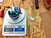
The HiMax Pro Motor installation.
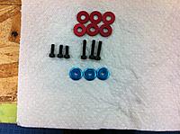
The complete motor assembly including connecters weighed 590.0g. The Motor installation was very straight forward. The only 2 things to note are, the motor needs 5mm spacers in order to have enough prop hub clearance and the M4 12mm bolts need to be changed to M4 20mm. |
«
Previous Thread
|
Next Thread
»
| Currently Active Users Viewing This Thread: 1 (0 members and 1 guests) | |
| Thread Tools | |
 Similar Threads
|
|||||
| Category | Thread | Thread Starter | Forum | Replies | Last Post |
| VIDEO; Extreme Flight 88inch Yak 54 | Donatas | General Discussion | 24 | 11-01-2008 02:15 PM | |
| REAL FLIGHT G4 !!!!!FIASCO!!!!! | folgado | Flight Simulators | 43 | 08-19-2008 04:22 PM | |
| Bayside RC Fun Fly 6/8 Fremont, CA | Ran D. St. Clair | Event Announcements and Discussion | 0 | 04-15-2008 08:53 PM | |
| Flight Sim X | Sukhoikid | Flight Simulators | 10 | 02-28-2008 08:39 AM | |
| Extreme Flight 110" Yak 54 Maiden Videos | The Flyin Hawaiian | General Discussion | 11 | 12-31-2007 07:40 AM | |


