logo
Thread Tools
Old 04-05-2019, 08:44 PM
JoeT is offline
Find More Posts by JoeT
Racer, Flyer, Dad!
JoeT's Avatar
Canada, ON, Vaughan
Joined Oct 2013
1,708 Posts
John C,

The question I posed was not intended to stir the pot, I know you and I know that you do lots of testing and are impartial. Hence the serious question.

The hypothesis for the noise could be related to the switching regulator on the power supply. The only way to really know is to throw it on a scope and see the frequency of the oscillations.

But I also agree with you that putting stuff in an oven without load serves no purpose.

Thanks
JoeT is offline Find More Posts by JoeT
Reply With Quote Quick reply to this message
Sign up now
to remove ads between posts
Old 04-05-2019, 08:47 PM
hpdrifter is offline
Find More Posts by hpdrifter
Registered User
United States, UT, Park City
Joined Mar 2009
144 Posts
abc
hpdrifter is offline Find More Posts by hpdrifter
Last edited by hpdrifter; 04-07-2019 at 03:52 PM.
Reply With Quote Quick reply to this message
Old 04-05-2019, 09:02 PM
JoeT is offline
Find More Posts by JoeT
Racer, Flyer, Dad!
JoeT's Avatar
Canada, ON, Vaughan
Joined Oct 2013
1,708 Posts
Quote:
Originally Posted by hpdrifter View Post
"Everybody should should stop baking their CBs and RX!"
What about those people flying in Arizona in 100F or more? They're baking everything.


"What does it prove if you don't have current and servo and everything else going!!!! Bad RF ... bad plastic odours, pissed off wives....."
I have done another test, this time with servo connected and everything else going.
What load and how much wattage draw?
JoeT is offline Find More Posts by JoeT
Reply With Quote Quick reply to this message
Old 04-05-2019, 10:06 PM
hpdrifter is offline
Find More Posts by hpdrifter
Registered User
United States, UT, Park City
Joined Mar 2009
144 Posts
abc
hpdrifter is offline Find More Posts by hpdrifter
Last edited by hpdrifter; 04-07-2019 at 04:03 PM.
Reply With Quote Quick reply to this message
Old 04-05-2019, 10:26 PM
cravenjw is offline
Find More Posts by cravenjw
Registered User
Joined Jul 2012
24 Posts
Quote:
Originally Posted by JoeT View Post
HPDrifer, seems like you have the propensity to extract minimal information and interpret things a bit off.

Here's a sample of what research can do, done by the same Cravenjw that posted on this thread.
https://www.rcgroups.com/forums/show...7&postcount=13

To add to cravenjw's comment on BLS172 Stalled, the 4.2 amps is within the range, but most digital servos do reduce the draw at "Stall" and have higher amperage draw during movement, in particular when accelerating to a different position. The BLS172 can draw up to 6 amps while changing direction which reduces to 4.2 ish amps at stall.

As was discovered by cravenjw (John C), this is the spec sheet of the polyfuse. Personally i'd trust the manufacturer of the polyfuse before I trust "marketecture".

https://www.rcgroups.com/forums/show...3&d=1547739906

The Table2 performance ratings in the .pdf sheet provided by the linked post is very telling.
Note, the tests and specs are done on 12V.

Table 2 indicates that at 60 degrees C, the hold amperage @ 12v is 2 amps, trip voltage is 4 amps.

Now you can work on the math of what unit of work would trip the polyfuse in an ideal world. (it would be much lower).

Putting something in an oven does nothing, unless you can also simulate load at a given voltage and temperature.
We only get two data points from servo vendors.
Stalled torque and full speed no load.
Both are useless in practice.
We do all our flying in between those limits, if you aren't then you doing something wrong!

I agree with Joe, the BLS172sv stalled draws 4.2A by multimeter or CB200 current telem. Most of the big 500-600oz-in 2nd gen brushless monsters behave the same, BLS172, 777, savox brushless. If you look at BLS172 power with a 1 mOhm shunt resistor, and watch the voltage across the shunt with an oscilloscope, the peak current is about 7.2A.

The newer MKS and Hitecs i have not measured, stalled or dynamic. I hear, the peaks can be 12-16A!!!

as for the RCG polyfuse data:
This data was from the datasheets before i started testing the polyfuses in the CB200. I will say the fuses in the CB under perform the specs on the datasheet (if the data sheet is read correctly, which is actually not easy, and most people interpret incorrectly).

I will post one set of measurements. I not going to going into lots of details now or here. If i do, it will be on RCG.

For a test, i attached a 1ohm power resistor a CB200 port. The resistor was connected in series with a MOSFET, so i could pulse the 1ohm load at 333Hz with varying duty cycles. The peak current was 7.85amp. This was as close to the 7.2A 333Hz PWM measurement from the BLS172 that i could simulate.

Then with the CB200 PCB removed from its case, at 20C ambient, i increased the duty cycle in steps.
I recorded CB200 current with the CB200. I recorded the polyfuse temp with a thermal camera.
I waited about 10min after each step for the polyfuse temp to stabilize or trip.


Here is the results;

Name: SteadyTestChart.png
Views: 96
Size: 38.7 KB
Description:

just before the trip
Name: Before Trip.png
Views: 94
Size: 359.0 KB
Description:

after the trip and reset
Name: After Trip and Reset.png
Views: 95
Size: 275.1 KB
Description:


at 3.8A average (7.2A pulses at 333Hz) the polyfuse temperature reached 85C but held indefinitely (10mins).

increasing from there, to 4.4A the fuse tripped and shot up to 125C within seconds.

90-95C is the point where the fuse gets unstable, and the slightest thing trips it.

Based on my measurements about 4A is the continuous limit. I mean 4A average (based on a servo like pulsing at 7.2A 333Hz PWM).

I also measured how long does it takes to trip if i applied the 1ohm load No PWM. Just 100% on. This give a 7.85A DC load at CB200 input voltage of 8V.

With the CB200 at ambient of 22C. It took 3.75s for the fuse to trip.

Name: Repeated 7A trips every 20s - first trip.png
Views: 86
Size: 48.3 KB
Description:


When a polyfuse trip, the crystal structure of the polymer changes for glass like, when they reset, the crystal don't reform quite a clean as a virgin fuse.
They have higher resistance after recovery. Not crazy different. But enough to notice. It can take days to weeks to fully recover.
Until then, they trip a little lower or faster!

So i made a setup that tripped to fuse repeated every 20s. By the 7th trips, the 7.85A load only took 2s to trip the fuse.

Repeated trips.
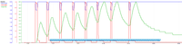
Name: Repeated 7A trips every 20s.png
Views: 91
Size: 87.7 KB
Description:

Close up of 7th trip.
Name: Repeated 7A trips every 20s - 7th trip.png
Views: 90
Size: 42.1 KB
Description:


I am sure that this thread will spiral out of control shortly. LOL

Remember, the CB200 is rated for 15A continuous. My steady state test, i put 4A to one of 15 ports/fuses.
During that to 4 ports simultaneously, is over the spec of the box.

The other CB200 spec of 90A peak for 2s, is a little harder to interpret.

Should we think of it a 6A peak for 2s over 15 ports/fuses?
If so, the my 7,85A for 4s trip, and even my 7th 2s trip time fits.

But i have thought about this peak spec a lot, and i have really no idea how is really applies to the connectors or the MOSFETs or the polyfuses in the CB200 and what is the limiting feature makes the spec 90A for 2s.

.
.
.

We reached the point in a number of my other threads where the audience spins out of control and the hysteria takes over! So let me ask a question before the that starts.

In my first test, i was supplying 8V to the CB, it held to 4A and was stepped there over 90mins under significant loads!
At its peak, the load was drawing 30W for the last 10mins!

Does anybody have a servo that will last more than 1min at 30W in a wing or elev? on a 100F day?
cravenjw is offline Find More Posts by cravenjw
Last edited by cravenjw; 04-06-2019 at 12:06 AM.
Reply With Quote Quick reply to this message
Old 04-05-2019, 10:39 PM
cravenjw is offline
Find More Posts by cravenjw
Registered User
Joined Jul 2012
24 Posts
Quote:
Originally Posted by JoeT View Post
John C,

The question I posed was not intended to stir the pot, I know you and I know that you do lots of testing and are impartial. Hence the serious question.

The hypothesis for the noise could be related to the switching regulator on the power supply. The only way to really know is to throw it on a scope and see the frequency of the oscillations.

But I also agree with you that putting stuff in an oven without load serves no purpose.

Thanks
There are no regulars on the CB200.

While we are on the topic, lets make sure we understand the CB series.

The backends and polyfuses are basically identical. Just the number of ports (and fuses) is different.

What is real different is the front ends.

The CB100 has a single bat input. No swtiching (on/off).

The CB200 has a two bat inputs. Both inputs are switch on and off with pair of MOSFET switching circuits. Both these circuits feed a bat sharing circuit the pics the bat with the higher voltage or both if they are close in voltage. The sharing circuit uses another pair of MOSFETs to select either of both bats. From what i can tell, a difference of about 50mV will cut off one bat.

The CB400 has two bat inputs and two regulator circuits. I have spent a lot of time looking at how they combine the regulator outputs.


So there is no "switching regulator" noise in the CB200.
cravenjw is offline Find More Posts by cravenjw
Last edited by cravenjw; 04-06-2019 at 06:47 AM.
Reply With Quote Quick reply to this message
Old 04-05-2019, 10:47 PM
JoeT is offline
Find More Posts by JoeT
Racer, Flyer, Dad!
JoeT's Avatar
Canada, ON, Vaughan
Joined Oct 2013
1,708 Posts
Quote:
Originally Posted by hpdrifter View Post
I wanted to simulate the actual situation when flying my Krill 33% SU-29/DA100 in extreme heat conditions. Hitec 5955 servo, max amperage I could create was around 3.5A. When fully stalled, it dropped to 2.9-3A. In actual flight, I have never recorded more than 1.8A on one servo (MUI30 connected between servo and CB200). the Battery is 2 cell 2300 A123 6.6V. So, wattage should be 23.1W right? Will post the screenshots tomorrow.


Both Joe and buckeyeflyer were complaining about poly fuses tripping. Neither of them showed any record of it.
Reality is, most telemetry sampling rates are not accurate enough to measure properly. They are mostly used for general reference so to trip a function, alarm or voice of some sort. Other than temp, RPM and some GPS, sampling rates are too slow.

The test that John put together is more accurate, and confirms stall torque amperage draw vs transient movement amperage draw.

Yes the new MKS servos have a higher peak amperage draw, I'm waiting for them to arrive so I can put them through the same barrage of tests.
JoeT is offline Find More Posts by JoeT
Reply With Quote Quick reply to this message
Old 04-05-2019, 10:48 PM
JoeT is offline
Find More Posts by JoeT
Racer, Flyer, Dad!
JoeT's Avatar
Canada, ON, Vaughan
Joined Oct 2013
1,708 Posts
Quote:
Originally Posted by cravenjw View Post
There are no regulars on the CB200.

While we are on the topic, let make sure we understand the CB series.

The backends and polyfuses are basically identical. Just the number of ports (and fuses) is different.

What is really different is the front ends.

The CB100 has a single bat input. This input is switched on and off with MOSFET switching circuit.

The CB200 has a two bat inputs. Both inputs are switch on and off with pair of MOSFET switching circuits. Both these circuits feed a bat sharing circuit the pics the bat with the higher voltage or both if they are close in voltage. The sharing circuit uses another pair of MOSFETs to select either of both bats. From what i can tell, a difference of about 50mV will cut off one bat.

The CB400 has two bat inputs and two regulator circuits. I have spent a lot of time looking at how they combine the regulator outputs.
No regulators.. interesting, so what could be causing the noisy RF?
JoeT is offline Find More Posts by JoeT
Reply With Quote Quick reply to this message
Old 04-05-2019, 10:49 PM
flyrcjoe13 is offline
Find More Posts by flyrcjoe13
Flyrcjoe’s work shop
flyrcjoe13's Avatar
United States, UT, Plain City
Joined Dec 2006
596 Posts
Quote:
Originally Posted by Esprit Model View Post
Congratulations to your 1999 solution, but we moved on.
Splitting 1/2 and 1/2 model due to obsolete equipment is soo 72MHz solution. I even sold my glow Saito, nice to look at, greasy and dirty as s....

Central Box 200 w/2x Receivers, Magnetic Switch (24ch.) $269.00
2x R7008SB 2x $165.00 = $330.00
More Expensive, Less Channels, Less Functionality = Futuba


I guess it's soo nice NOT to have this discussion with Futaba equipment, because Futaba DOES NOT have any equipment like this.

- I do not use V for Rx packs only (Very silly with LiFe) I use Capacity for Both Packs/ Max Amp, Voltage is secondary data
- I have passive alarms for Capacity/Over temp/Over Amp...

At least with Futaba they can use their equipment and fly their planes without worry of failure due to poor products and miss advertisement. When you put out as much money as I did on this project you call the companies direct and speak to them over and over to make sure their system is compatible with your application. I did this over and over and was told it would work and how to put it all together. Now being told after spending all this money that I was lied to and that it is set up to fail and possible crash is very upsetting. Again at least with Futaba you would have customer service and support. So in the long run I bet it would have been a cheaper and more effective route to go with Futaba but with the promises I had from Danny and James I thought I was making the right decision. I had even started into another plane build that was also being built to run the Jets system. I am a couple thousand dollars into that build too that is now at a complete stand still. The unfortunate part is that ZB is the distributor in the US so in effect you are buying from him no matter who you purchase it from. The poor support and service starts at the topic and goes down. If only any of these people who say I’m wrong would put there money where their mouth is and prove they trust it by buying all of this from me then we could all just move on. The CUB is now for sale too. They can have a packaged plane ready to fly.

These cost break down sheets don’t even included the countless hours of my time that I spent on everything.
flyrcjoe13 is offline Find More Posts by flyrcjoe13
Reply With Quote Quick reply to this message
Old 04-05-2019, 10:58 PM
cravenjw is offline
Find More Posts by cravenjw
Registered User
Joined Jul 2012
24 Posts
Quote:
Originally Posted by JoeT View Post
No regulators.. interesting, so what could be causing the noisy RF?
The servos!
The RF noise was there in the test with the Hitec RX running direct on the lipo! There was no CB200. There wasn't even Jeti!
cravenjw is offline Find More Posts by cravenjw
Reply With Quote Quick reply to this message
Old 04-05-2019, 11:16 PM
cravenjw is offline
Find More Posts by cravenjw
Registered User
Joined Jul 2012
24 Posts
Quote:
Originally Posted by JoeT View Post
Reality is, most telemetry sampling rates are not accurate enough to measure properly. They are mostly used for general reference so to trip a function, alarm or voice of some sort. Other than temp, RPM and some GPS, sampling rates are too slow.

The test that John put together is more accurate, and confirms stall torque amperage draw vs transient movement amperage draw.

Yes the new MKS servos have a higher peak amperage draw, I'm waiting for them to arrive so I can put them through the same barrage of tests.
JoeT is correct. I have posted about Jeti sampling rates on RCG so many times its ridiculous. CB200 data comes in at 3-4Hz (when reception is good).

Most peaks and valleys are missed!

However, there is a one trick that is very valuable.

The CBXXX samples at the RF rate (100Hz). Its stores the max/min values internally. When you land, you can go into the CBXXX thru device explorer and see those values.

You can also create a Jetibox display. First you navigate the Jetibox menu to the CB200 and the min/max value you want to view. When you return to the normal pages of telem displays, the one linked to the Jetibox will continuously display the max/min screen you previous navigated to (while the TX remains on).

Jetibox screens is text, its no telem and its not logged.
But it is possible see the peaks live.

Here's a vid, its not about current, but the current data is in the same place.

Jeti CB200 Diagnostics (10 min 18 sec)
cravenjw is offline Find More Posts by cravenjw
Reply With Quote Quick reply to this message
Old 04-05-2019, 11:24 PM
flyrcjoe13 is offline
Find More Posts by flyrcjoe13
Flyrcjoe’s work shop
flyrcjoe13's Avatar
United States, UT, Plain City
Joined Dec 2006
596 Posts
Quote:
Originally Posted by cravenjw View Post
I am not disputing that you had issues, and been able to document some combinations of components and/or setup(s) where something is definitely wrong.

But i would like to address, your "good RF and bad RF"
Lets talk about "good science and bad science" or "good root cause analysis and bad"

I am going start with your "tool", the MJF-852 A/C LINE NOISE METER

Manual

In case you don't want to go read the manual, this device is intended to find arcing in AC power lines.

So back to the "good bad stuff"

In the video, at about 19:10, Joe states "this is a directional antenna, where ever you point it is going to show you where the most is"

This is completely wrong! The exact opposite is true. The antenna on the MJF-852 is a dipole antenna. Dipole antennas are omnidirectional antennas, not directional.

If you read the manual, or your have any clue about how to arrange antennas in an RC model, you know that an omnidirectional antenna radiation (and reception) pattern is toriodal or donut shape around the antenna, and that there is a null in the direction of the antenna (or along the axis of the antenna)!

The 852 meter gives high signal when the noise source is perpendicular to the antenna. To clearly identify the source you then point the antenna (ie point the null) at the suspected source and the signal should decrease from the perpendicular maximum.

From the manual,
Attachment 1208923

Just to cover the all the bases, MJF does make the 856 meter, which has a 3 element yagi antenna that is directional, and the opposite of the 852.
The 856 reads high when pointed at the source and low when perpendicular.

But as for Joe's interpretation of "good and bad rf", i really think we should all be very careful about any of his conclusions.
He definitely has had some setup problems!
However, he clearly has no idea how to use the only measurement tool in the video and upon which he bases some of his RF conclusions.
This is "bad science" or "bad root cause analysis".
I will stand behind my findings in my video. I have been using the RF meter for over 18 years. I have been able to diagnose hundreds of problems in planes including bad ignitions, bad Servos, bad wires etc. The person who turned me onto this was the old owner of C & H ignitions. Everybody who has had me check over their plane and has seen how easy it is to find their problems, knows that a line noise analyzer does find the issue and it does work. Even in the diagram you posted it clearly shows them pointing the end of the antenna towards the problem. As I showed in the video it does work just like your diagram shows. I have even had in-depth conversations with a professors at MIT who said that I am absolutely correct in my use of the tool. In the conversation I explained to him my findings of good RF and bad RF and he said I explained it correctly, and that my understand of RF is correct. If you have bad RF in your airplane it will cut down on your signal strengths. So tell me again how I am so wrong when even an MIT professor says I am correct? The frequency does not matter with this tool, it does detect the issues.
How many times did you have to send back your cb200, you told me three. And come to find out you had a bad spark plug the whole time. My meter would have found that right away (as it has many times before). Imagine the lack of headache had you used this simple tool. Why didn’t you pull out all of your fancy tools that you have and figure it out before sending your cb200 back the first time, let alone the second or even third time?
flyrcjoe13 is offline Find More Posts by flyrcjoe13
Reply With Quote Quick reply to this message
Old 04-05-2019, 11:33 PM
flyrcjoe13 is offline
Find More Posts by flyrcjoe13
Flyrcjoe’s work shop
flyrcjoe13's Avatar
United States, UT, Plain City
Joined Dec 2006
596 Posts
Quote:
Originally Posted by hpdrifter View Post
According to CB200's poly fuses specs, the tripping temperature should be 80C or 176F. So I put CB200 in my post-curing oven to see if it is true. Probably is. At 50C or 122F, the box got pretty hot so I stopped. As you can see, at 50C nothing tripped. In the Video, Joe says the poly fuses trip at 32C which is wrong.
If you believe in this product so much to put things in your oven to try and discredit me why not just drive down to my house and buy all my stuff to prove yourself? Also please tell me how your test is even valid since you did not put any kind of a load on it at the time of testing? Also where is the video?
flyrcjoe13 is offline Find More Posts by flyrcjoe13
Reply With Quote Quick reply to this message
Old 04-05-2019, 11:43 PM
cravenjw is offline
Find More Posts by cravenjw
Registered User
Joined Jul 2012
24 Posts
Quote:
Originally Posted by flyrcjoe13 View Post
I will stand behind my findings in my video. I have been using the RF meter for over 18 years. I have been able to diagnose hundreds of problems in planes including bad ignitions, bad Servos, bad wires etc. The person who turned me onto this was the old owner of C & H ignitions. Everybody who has had me check over their plane and has seen how easy it is to find their problems, knows that a line noise analyzer does find the issue and it does work. Even in the diagram you posted it clearly shows them pointing the end of the antenna towards the problem. As I showed in the video it does work just like your diagram shows. I have even had in-depth conversations with a professors at MIT who said that I am absolutely correct in my use of the tool. In the conversation I explained to him my findings of good RF and bad RF and he said I explained it correctly, and that my understand of RF is correct. If you have bad RF in your airplane it will cut down on your signal strengths. So tell me again how I am so wrong when even an MIT professor says I am correct? The frequency does not matter with this tool, it does detect the issues.
How many times did you have to send back your cb200, you told me three. And come to find out you had a bad spark plug the whole time. My meter would have found that right away (as it has many times before). Imagine the lack of headache had you used this simple tool. Why didn’t you pull out all of your fancy tools that you have and figure it out before sending your cb200 back the first time, let alone the second or even third time?
You are misquoting me. I have never sent back a CB or any Jeti component.

You ask me if i believe ignition could generate RF problem that would bring down a plane.

I told you that i did see a crash that in the end was found to be a result of a cracked ceramic insulator on a spark plug. The owner had multiple events taxing to take off or just takeoff.

The user returned his tx/rx to esprit. It wasnt a CB. It was before the CB was released! Esprit did a check out. They said they couldn't find anything. They sent him back all new gear.

His first flight back with all new gear, the plane took off, and completely confident with all new gear, he pulled vertical, and it went lights out at 100ft, it came straight down. Totally spinner dip, with me watching.

Myself and two other spent 2hrs playing with the electrically live wreckage. Eventually, we found loads of carbon in one plug boot and plug. When we wiped the carbon on the plug the hairline crack showed in the white insulator.

Final verdict was the crack was there for awhile. Before the Jeti return/replacement. That at startup it was tight, and it took a bit of run time to heat to open and when it did the arcing started, which was repeatedly just before after take off.

Jeti is definitely not immune to ignition arcing problems. I don't think any RC system is either.

The owner flew hundreds of flight on the same tx/rx after that without issue that i know of.
cravenjw is offline Find More Posts by cravenjw
Last edited by cravenjw; 04-05-2019 at 11:53 PM.
Reply With Quote Quick reply to this message
Old 04-05-2019, 11:57 PM
flyrcjoe13 is offline
Find More Posts by flyrcjoe13
Flyrcjoe’s work shop
flyrcjoe13's Avatar
United States, UT, Plain City
Joined Dec 2006
596 Posts
I would actually like to take time to thank Cravenjw/John and hpdrifter/Ed for their phone calls to explain to me that the problem does exist in the cb400 and CB100 as well. They were kind enough to tell me that the CB400 and even the CB100 have poly fuses also. They were able to point out that James and Danny had both misspoke when they were explaining to me that the cb200 was the only product with said poly fuses. I appreciate that Danny and James asked John and Ed to contact me and even giving them my personal email address to do so. Asking them to set me straight in my understanding. You sure have done that, you have clarified all of the mistruths that I was being told by Danny and James. Sure would have been nice of them to ask me before giving out my info to have people harass me. I also find it funny that when talking to all four of you and you would start down your paths of stories, lies and excuses you would start to loose your words and in effect stutter in your speaking. (Let me make myself very clear, I am NOT making fun of any speech impediment or medical issue!) It started making it easy for me to tell when you were being honest and truthful and when you weren’t. I hope you can understand why I may not have been the nicest person to speak with given the circumstances. So which one of you is going to prove yourself and buy my stuff so we can all go on our way. Then you can have all the products you need to test and replicate everything the right way.
flyrcjoe13 is offline Find More Posts by flyrcjoe13
Reply With Quote Quick reply to this message


Quick Reply
Message:


Currently Active Users Viewing This Thread: 3 (0 members and 3 guests)
 
Thread Tools