|
|
|
|
|
Build Log
Gee Bee Z Wendell Hostetler 1/3 Scale
We are building the Wendell Hostetler 1/3 scale version from National Kit Cutters with a Saito FG-100TS for power. The plane will be covered in Oratex and painted with Klass Kote paint. If you are building one of these planes, please share some pictures and ideals.
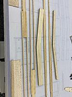
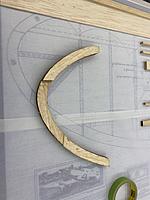
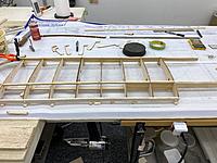
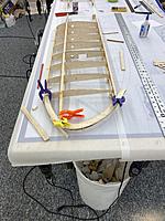
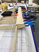
The Gee Bee Z was designed and built (in six weeks) in 1931 by the Granville Brothers and Robert Hall to try and win some of the prize money at the Thompson Trophy Race. Their aircraft business was struggling due to the depression and the races looked like a way to make some money and pull through. The Gee Bee Z was the first in a series of race planes for the small company. It was powered by a Pratt & Whitney 535 HP Wasp Junior radial engine. Can you imagine a 535 HP engine on a 23í 6Ē wingspan aircraft in 1931? If that wasnít enough after sweeping the Thompson Trophy races, they went back and mounted a 750 HP Wasp Senior engine on this little Black and Yellow beauty. Lowell Bayles was attempting a world speed record when the right wing broke off causing a fatal crash. For such a short life, this plane has a lot of history, Google it, it makes for some very interesting reading there is also some filmed interviews that share a lot of inside information on the Granville Brothers like the name Gee Bee is their initials on all of their race planes. Enough about this little speed demon letís build an aircraft. I started with the Wing spar boxes and the spar joiners. Fit the spars in the boxes and remove after they are clamped this will assure a good tight fit. Wipe off any epoxy on the spars and let the boxes dry. Next the wing tips were built before laying out the wings on the plans. Once the wings were built over the plans the wingtips could be fit without moving the wings. I chose to cut spacer blocks to set the wing washout instead of using the tabs on the ribs. This is my first build thread so please give me feed back and let me know what you like or would like to see. Enjoy it's a Great Hobby! Dennis |
|
|
|
|
|
|
|
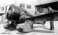
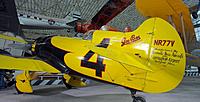
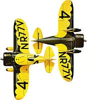
A few pictures of the full scale Gee Bee Z
|
|
|
|
|
|
I will be following Dennis. I know anything you build will be top notch.
|
|
|
|
|
United States, NY, Wading River
Joined Jan 2006
4,494 Posts
|
Very nice Dennis, itís not an easy one. I am also building one And am about 75% done with the fuse. Lots of head scratching with this build. Hostetler plans are not the most detailed out there.
|
|
|
|
|
United States, NY, Wading River
Joined Jan 2006
4,494 Posts
|
Just an FYI, former 6A is incorrect and has to be re-cut. Iíve confirmed with several who have built the plane.
|
|
|
|
|
|
One note I forgot to mention, the rear wing spar is capped with 1/8Ē x 1/4Ē Basswood. Be sure to stop the cap strips between W5 and W6. The spar will be too thick for W6 with the cap strips.
I also had the add balsa caps on the spars to fill in the gap at the top of the ribs. These were sanded flush with the ribs and give a nice fit for the leading-edge sheeting. |
|
|
|
|
|
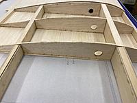
After the sheeting has dried the wing leading edge and the trailing edge for the ailerons can be added. Next the servo bays and the rib cap strips can be added. After a little sanding the ailerons can be built and hinged.
|
|
|
|
|
|
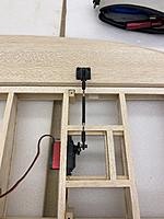
Once the ailerons are built and fitted to the wing the birch plywood control horn mount can be installed and the aileron linkage setup.
|
|
|
|
|
|
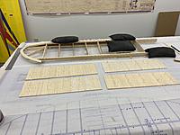
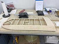
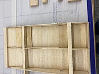
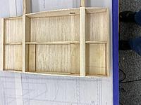
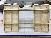
Now we have a complete set of wings the center section can be built. Plug both wings into the wing spars this will assure they are parallel and spaced properly. Place one wing over the plans and align the spar boxes with the plans. With the bottom center section sheeting prepared. Build the first side of the center section. Be careful not to glue the outer rib of the center section to the wing. Use parchment paper to keep them separated while aligning and tack gluing for perfect alignment. After the first half is built do the same for the other wing. After both sides are framed up sand the assembly. Now we are ready to install the landing gear blocks.
|
|
|
|
|
|
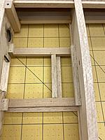
The plans show small plywood blocks for the landing gear mounts. I chose to cut new ones the full width of the bay between ribs. Once the epoxy is dry the gear can be aligned and blind nuts installed. The balsa backer blocks can be installed next, be sure to cut reliefs for the blind nuts.
I used masking tape to mark the wing and align the landing gear. Once the gear is mounted. Mark the flanges with a pen and cut away the balsa so the gear sits directly on the plywood plates and the spar boxes. |
|
|
|
|
|
.OOps ,sorry
|
|
|
|
|
|
Alright with the center section fully sheeted and the leading edge attached and sanded. I decided to go ahead and fit the wheel pants since it would be easy to get to without the fuselage in the way.
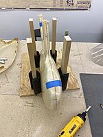
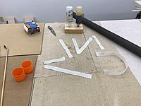
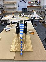
The wheel pants come split down the center but, do not have a flange to fasten them together. I marked them left and right and decided to put the flange on the inner pant. Use packing tape and line the inside of the outer pant along the dividing line and spray some Pam on it. Now tape the pants together being careful to get the best alignment possible. Once both are taped together it's time to lay 9 ounce x 1" wide glass tape in for the flange. I made a simple jig to hold the pant while working the tape in place. Cut strips to length and lay them out so you can easily identify which one goes in next. I used wooden dowels one with an epoxy brush and the other with a pin to work inside the pants and position the fiberglass tape. |
|
|
|
|
|
Plywood blocks need to be installed on the new fiberglass tape that was just installed for the screws. Cut 1/8" Birch plywood to suit the size. and epoxy in place. Once the plywood blocks are in place. Tape the wheel pants back together, layout the screw holes and drill them. I used #1 x 1/4" sheet metal screws for the pant seam.
|
«
Previous Thread
|
Next Thread
»
| Currently Active Users Viewing This Thread: 1 (0 members and 1 guests) | |
| Thread Tools | |

