logo
Thread Tools
Old 10-28-2016, 10:35 PM
Jaketab is offline
Find More Posts by Jaketab
Escape From Gravity!
Jaketab's Avatar
United States, WV, Charleston
Joined Aug 2007
754 Posts
This brings me to the last post of the evening. Almost caught up posting pics of build to date. Tomorrows task is the install the rudder horn. Had to come up with an idea to center the horn exactly on the money. You can see the horn placed on with the jig on the test bitch rudder.

J Tab
Jaketab is offline Find More Posts by Jaketab
Reply With Quote Quick reply to this message
Sign up now
to remove ads between posts
Old 10-28-2016, 10:39 PM
Jaketab is offline
Find More Posts by Jaketab
Escape From Gravity!
Jaketab's Avatar
United States, WV, Charleston
Joined Aug 2007
754 Posts
With regard to the rudder horn and servo bellcrank, the horn is 3.625" and the bellcrank is 2.5".
Cables will be parallel. The set up give better mechanical advantage. The tension on the cables will be even at full throw. The bellcrank is a straight arm. The rudder horn is offset .015" on the aft side of the rudder hinge.
Jaketab is offline Find More Posts by Jaketab
Reply With Quote Quick reply to this message
Old 10-29-2016, 08:28 AM
acerc is offline
Find More Posts by acerc
Registered User
acerc's Avatar
United States, FL, Center Hill
Joined Jul 2014
2,167 Posts
WOW! One day and your 80% done... LOL!!!! As usual, very nice work.
acerc is offline Find More Posts by acerc
Reply With Quote Quick reply to this message
Old 10-30-2016, 03:22 PM
Jaketab is offline
Find More Posts by Jaketab
Escape From Gravity!
Jaketab's Avatar
United States, WV, Charleston
Joined Aug 2007
754 Posts
Worked on the motor box and set the horns in the rudder today.
As the motor box comes with the kit, it goes together with 3 mil light ply. It has the correct thrust angles built in which makes it a good base to build on. The instructions require several layers of glass to strengthen. Instead I'm using 1/8 plywood to sandwich a layer of 2 oz glass between, and another layer of glass on the outside. The front and base of the box will be increased to about 1/2".

The rudder horns, as with all the control horns, are set with Hysol 9462. The jig holds the horn in place in the exact position. If calculations are correct, the pull cables will have the same tension throughout the range of throw.

Regards - J Tab
Jaketab is offline Find More Posts by Jaketab
Reply With Quote Quick reply to this message
Old 10-30-2016, 03:41 PM
Jaketab is offline
Find More Posts by Jaketab
Escape From Gravity!
Jaketab's Avatar
United States, WV, Charleston
Joined Aug 2007
754 Posts
Almost ready to cover stabs and elevators.
The Red Devils in the picture is the one I'm chasing after.

J Tab
Jaketab is offline Find More Posts by Jaketab
Reply With Quote Quick reply to this message
Old 10-30-2016, 06:56 PM
Hinckley Bill is offline
Find More Posts by Hinckley Bill
Registered User
Hinckley Bill's Avatar
Hinckley Illinois
Joined Jan 2006
2,992 Posts
Quote:
Originally Posted by Jaketab View Post
Worked on the motor box and set the horns in the rudder today.
As the motor box comes with the kit, it goes together with 3 mil light ply. It has the correct thrust angles built in which makes it a good base to build on. The instructions require several layers of glass to strengthen. Instead I'm using 1/8 plywood to sandwich a layer of 2 oz glass between, and another layer of glass on the outside. The front and base of the box will be increased to about 1/2".

The rudder horns, as with all the control horns, are set with Hysol 9462. The jig holds the horn in place in the exact position. If calculations are correct, the pull cables will have the same tension throughout the range of throw.

Regards - J Tab
Thanks for sharing these wonderful tips, and the photos help immensely
Hinckley Bill is offline Find More Posts by Hinckley Bill
Reply With Quote Quick reply to this message
Old 10-31-2016, 05:08 PM
Jaketab is offline
Find More Posts by Jaketab
Escape From Gravity!
Jaketab's Avatar
United States, WV, Charleston
Joined Aug 2007
754 Posts
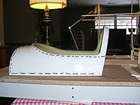
Todays work was to cut the lip from around the fiberglass canopy frame. This frame is made for the Christian Eagle and 50% Challenger as is and requires modification to fit the Pitts. One of the differences between the models is the front of the turtle deck is slanted back on the Eagle & Challenger. On the Pitts its more or less vertical.
The lip/shoulder on the front and underside needs to be removed so it will fit the wood frame.

Also cut rough openings in the engine cowl. I'm thinking about leaving the bottom half of the intakes to block off air from going under the cylinders. There will be a flat shelf on the bottom of the intake duct.
Jaketab is offline Find More Posts by Jaketab
Reply With Quote Quick reply to this message
Old 11-01-2016, 05:25 PM
acerc is offline
Find More Posts by acerc
Registered User
acerc's Avatar
United States, FL, Center Hill
Joined Jul 2014
2,167 Posts
I bypassed all the glass and went custom aluminum, but, mine was not designed as a hatch. Kinda wish it had been.
My Valach would not even get warm with the intakes completely open, 180° was max temp, of which really made for a sucky smoke trail. I have made some temporary baffles to slowly reposition as I find the sweet spot for normal operating temperature, currently running around 240°, very nice smoke. Once I know the amount of area to cover I'll make some that look more scale. Long story short, yes, the Valach will run real cool with those holes wide open.
acerc is offline Find More Posts by acerc
Reply With Quote Quick reply to this message
Old 11-01-2016, 10:46 PM
MattyMatt is offline
Find More Posts by MattyMatt
CARF-Models Rep USA
MattyMatt's Avatar
United States, NC, Greensboro
Joined Apr 2006
3,710 Posts
Looks great John.

One important thing. I know you are going to use the same flying wires as I on my challenger. Make sure you get them and put the plane together before you finish/cover it. The reason is the gap in the center section of the top wing. Without the wires tension, you should have a pretty sizable gap in the front/leading edge of the wing. If the center of the wings/root ribs are matching up perfectly with no tension, then you will end up with a very large gap at the root trailing edge when the wires are tensioned. The wires actually pull the wings slightly forward, causing a gap in the back.

I hope this makes sense. When I say a gap, I'm talking 3/8"+
MattyMatt is offline Find More Posts by MattyMatt
Reply With Quote Quick reply to this message
Old 11-02-2016, 07:18 AM
Jaketab is offline
Find More Posts by Jaketab
Escape From Gravity!
Jaketab's Avatar
United States, WV, Charleston
Joined Aug 2007
754 Posts
Ace and Matt,

Thanks for the input. Keep those tips coming please. I will have questions as I progress.
When running the Valach 210 on the bench stand, I kept an eye on the temps. The heads, (not the cylinders) climbed to about 270 where they leveled off. Based on that, I'm hoping some effective baffling and ductwork will keep the temps in 240 F range.

I installed some insurance (wing bolts) to keep the wings on the plane and to keep them from separating.

When I installed the upper wings, I found the wire attachment points on the cabane were placed too close to the bottom of the upper wing. The clips were digging into the bottom of the upper wing. To remedy, I made some short extension brackets. (Not in picture)
Jaketab is offline Find More Posts by Jaketab
Reply With Quote Quick reply to this message
Old 11-02-2016, 07:49 AM
acerc is offline
Find More Posts by acerc
Registered User
acerc's Avatar
United States, FL, Center Hill
Joined Jul 2014
2,167 Posts
Well done!!!!
acerc is offline Find More Posts by acerc
Reply With Quote Quick reply to this message
Old 11-02-2016, 07:53 AM
kork is offline
Find More Posts by kork
Registered User
kork's Avatar
United States, FL, North Port
Joined Nov 2011
1,054 Posts
Jake, where did you get your fast clips for the flying wires?
I only found them out of country?
Great job!
kork is offline Find More Posts by kork
Reply With Quote Quick reply to this message
Old 11-02-2016, 08:47 AM
Jaketab is offline
Find More Posts by Jaketab
Escape From Gravity!
Jaketab's Avatar
United States, WV, Charleston
Joined Aug 2007
754 Posts
Kork,

They came with the EMHW kit.
Try the below link. Or, Gotz Vogelsang may be able to direct you.

http://www.flying-wires.ch/flying-wires/index.html
Jaketab is offline Find More Posts by Jaketab
Reply With Quote Quick reply to this message
Old 11-02-2016, 09:33 AM
kork is offline
Find More Posts by kork
Registered User
kork's Avatar
United States, FL, North Port
Joined Nov 2011
1,054 Posts
thanks Jake, I have the challenger III and did not get those.
I will certainly order some from Gotz, they look bullet proof.
Are you using Aerobond on your kit?
kork is offline Find More Posts by kork
Reply With Quote Quick reply to this message
Old 11-02-2016, 10:27 AM
rcflyguy is offline
Find More Posts by rcflyguy
workin on rollers!!!
rcflyguy's Avatar
Findlay, OH
Joined Jan 2006
2,203 Posts
Check with Bill Hempel. His 50% pitts uses the same hardware .
rcflyguy is offline Find More Posts by rcflyguy
Reply With Quote Quick reply to this message


Quick Reply
Message:


Currently Active Users Viewing This Thread: 1 (0 members and 1 guests)
 
Thread Tools