|
|
|
|
|
OK, getting this build back on the rails.......
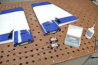
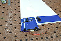
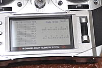
After setting up the rudder pull pull I moved onto the elevators. We previously installed the control horns so those were ready. Holes for the servo screws are already done so just harden them with thin CA before installing. Install the servos with the wire end facing the small relief for the front side. The elevator servos require two 48" or 52" extensions depending on where you are planning to install your receiver. The goal with all control surfaces is to: 1 - Use the smallest servo arm to get the job done. 2 - Never have the ball link closer to the hinge-line than the length of your servo arm. 3 - Avoid sub-trims like the plague. 4- Set so that your ATV's or servo travel are at least 120-140% to make the most use of servo resolution. That said I got these elevators mostly set up off the airplane and then installed for final setup. It is highly likely you will have to elongate the elevator horn slot to allow full travel. Also it is very important to set up these servos at or above what you intend to set up as your high rate. Once installed on the plane make absolutely certain your elevators match at very least the full up / down and center positions. If you have servo matching on your transmitter match them throughout their travel range to avoid unexpected flight characteristics. |
|
|
|
|
|
|
|
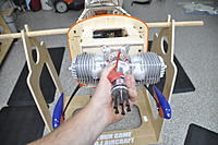
OK time to mount an engine!
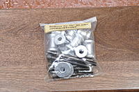
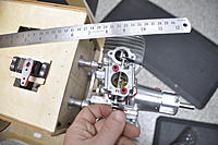
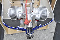
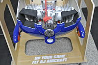
There is engine mounting hardware and standoffs included with the plane. There is also various screws left for installing canister baffles, engine box top, etc. Be sure to use some type of bonded waters on your cowl install to help keep it secure. I used different hardware to join my cowl halves so I stole a few from that. To tell what size standoffs you need you will install your cowl (make sure you remove the single center bolt at the bottom of the cowl!). Measure the distance to the firewall and add your spinner gap that you desire. Measure your engine from mounting plate to hub and subtract that. You are left with your standoff length. In my case 1" The engine mounting template fit just a bit too snug on the firewall so I gave both the L and R sides a pass with a sanding block, then it fit right in. Make sure that the horizontal and vertical laser registration marks are all lined up. Mark the holes and drill with a 1/4" drill bit. If you are ever leery that the engine may not line up, you can always drill one hole and mount the engine roughly to test the fit. In the case of this plane the template was perfect and the engine lined up first try. Install the engine with the bolts and a lockwasher through the engine mounting plate. Then a standoff and an optional fender washer to spread the load (not included). On the back side install the blind nuts and be sure to use thread-locker on these for final install. After engine is tight, I like to install a flat washer and a nylock nut on the inside of the firewall to securely lock the bolts in place for added protection. |
|
|
|
|
United States, WI, Fond du Lac
Joined Jan 2017
482 Posts
|
Hey Terry, I have a question for you if you dont mind... I see you are using a servo screw to hold down your rudder wire. On my 83" ARS I have to remove my rudder to transport it. I lube my rudder wire every morning before my first flight and it stays put until the 3rd or 4th flight and then the wire would start working its way out after that. I started using a strip of packing tape over the top of the rudder to hold the wire in. It works just fine and its simple, but I dont like pulling on the covering that hard every time I fly it to remove the tape. I do like the screw idea, I just dont see it holding up well to being removed and installed twice every single time I take it out to fly. I forsee a worn out stipped hole after a running the screw in and out a bunch of times... Im sure it is totally fine for a rudder that rarely gets removed though. What are your thoughts?
|
|
|
|
|
|
Next it's time to think ahead and do some planning. If you are installing canisters this is a good time, but with that you will also want to consider your throttle servo location. Likely with headers / cans that will be inside the engine box, where mufflers it can be on the bottom. Also a good time to consider your choke setup. Here I'm using a simple G10 arm I made and can access through the snorkel on the cowl.
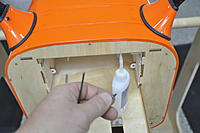
Since I'm using mufflers I'm going to mount my throttle servo in the bottom of the engine box with a reversed throttle arm on my DA carburetor (to point down instead of up). I also can install the bottom fuse plate with screws and bonded washers as well as final gear cuff installation. Otherwise I would do those both after canisters are installed. I cut the holes out of the bottom plate for air exit and saved the scraps. With that I made small covering disks to cover the screw holes after installation  Next I want to talk a bit about throttle servo installation. Lots of people get this wrong and end up doing a throttle curve to fix it. It's very important to use the longest arm or hole on the carburetor that is provided and the shortest servo arm possible with 1" being kind of a standard and 3/4" being ideal. It's also important to understand how the throttle range works. On all gas engines the actual "half throttle" does not occur with the carburetor plate half open. It's much much closer to 3/8 open. If you want half stick to be half throttle for a nice linear throttle movement throughout the range you will want half way to be in that area. If you want more throttle punch on the lower half then you can use half servo as half carburetor open. This is quite easy to calculate using a ruler and doing some math based on measurements from a fixed point (firewall) to the throttle arm hole. Also keep in mind that it is very important to keep your ATV's or servo travel as close as possible to the same at both full throttle and idle. Having them way off, say something like 20 at idle and 120 at full throttle can create an extremely undesirable curve in your throttle. Take your time with your throttle setup and you will be rewarded with a nice smooth linear throttle from idle to full.
|
|
|
||
|
|
Quote:
|
|
|
|
|
|
|
Next we're going to do some cowl cutting and do some air flow planning to give proper air entrance and exit from the engine area.
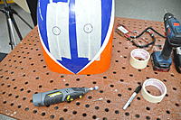
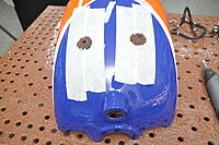
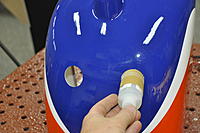
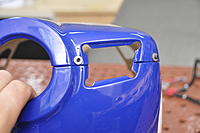
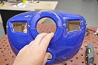
First for mufflers (if you are using any), pretty standard cowl cutting. I use an external template and also mark the inside. Start small, work your way out and test fit frequently so you don't get them off their desired position. Be sure to use masking tape to avoid chipping the paint. When final sizing and sanding, always try to use something other than a steady hand with a dremel or your fingers and sandpaper. Sandpaper around a bottle, dowel etc. for curves and sandpaper around a scrap of wood for straight lines works well. This will give you nice crisp cutouts every time. Now for air flow management. You will need to open the bottom of the cowl to get adequate air exit. On mine I fabricated a low pressure lip which is also extremely helpful in actually "sucking" or speeding up the flow of air out of the cowl. You can also create this with a creative foam lip, using the same materials s the baffles. People have also used aluminum strips or even sections of the cowl that were removed. Lots of ways to get this done but you will need some more air exit than the two holes in the fuse bottom. I chose to enlarge the holes to allow a bit more air coming into the cylinders to cool the engine better. I left about 3/32" of the lip inside. Baffling should not be considered optional, especially if you are flying 3D where your airspeed is slow to nothing. Even though in post stall you are barely working the engine it will get warm with lack of air-flow. For IMAC where you have constant straight shot air coming in you may get away with less aggressive actions as opening up the inlets. I did shoot a video on baffling which I will work on finalizing in a couple weeks but for now here are a series of pictures. I have also done a video on my youtube page previously but my new video will be much more detailed and descriptive. To find my old video search youtube for "terrysucstom baffling".
|
|
|
|
|
|
Next we'll mount the ignition. Be sure to protect the hall sensor wire from abrasion even through it has a protective cover. Secure wires and be sure to use a servo safety clip to keep the plug secure.
Also make sure you cover the spark plug wires with something to prevent damage. I prefer the split wire sleeves as they are the most flexible and don't stick to the braid like some wraps can. |
|
|
|
|
|
Use a laser pointer to locate the hole on the cowl so you can get it in the correct spot but also keep it as small as possible. I use a laser on a tripod but this can literally be as low tech as a dollar store laser pointer zip tied to a stick in the ground.
With the cowl off, get the laser pointed at the needles so it's clear of the mufflers etc. Then carefully (without moving the plane) install the cowl. Mark it with a sharpie, and then it's a good idea to remove the cowl and make sure you didn't move the plane. Drill the hole and voila. The most perfect needle access hole at the field!!! |
|
|
|
|
|
Next we'll take a look at the fuel system. I realize there are felt clunk haters out there but I have years without junk in my carb screen that say they are working fine for me.
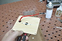
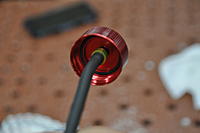
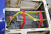
I like to modify the taildragger fuel tank by installing Viton line inside the tank. I thin insert the brass rod into the Viton with a couple drops of redline for lube. Push it in with an Allen wrench so it's centered. I use a small section of fuel line for a clap on both ends after installing it. Always check the fittings on the top and make sure they are aimed correctly and snugly installed. I start by installing the vent line in the bottom of the plane, I like to use a section of brass tube to go through any structure on the bottom of the plane. I then install a section of fuel line on the end of that. I like to put the fuel vent line on the side of the plane that my fuel dot is to make it easier to see when it's full as well. Also make sure to protect this line from abrasion especially coming through the carbon reinforced floor plate. I do not like using foam or other materials under my fuel tank so I use adhesive backed velcro strips and velcro wraps to secure it into the plane. Fuel fill line is secured to the included fuel dot or your choice of fuel dot. |
|
|
|
|
|
Next it's time to wire the inside of the plane, plan your setup in advance leaving final battery location until everything else is installed and finished. I made a platform for the RX which worked out nicely and I did end up installing my batteries on a platform fabricated above the fuel tank. After more test flights and I find my final CG I will post further data on this.
|
|
|
|
|
|
I also tend to leave my aileron servos install and balancing until basically last. It's normally the first time my plane is on the ground after I start building, and also these are fixed items that don't effect CG so their placement is not optional.
I shot a new video describing servo balancing, if you have questions in the mean time shoot me a PM and I'm glad to help you! |
|
|
|||
|
|
I got to maiden the plane even though I was short a spinner bolt and it looks like the ideal CG for neutral flight will be about 1/4" or so in front of the tube. 3/4" in front of the tube is recommended by Andrew and will give you the absolute most precision out of your ARS. I found mine without the spinner to be a little too neutral and it still flew absolutely amazing and clean with very little rudder coupling. I am anxious to fly it again this week with the added couple ounces of spinner on the nose (y)
|
||
|
|
||
|
|
Quote:
I'm waiting for a new spinner bolt to finalise CG before publishing my AUW. |
|
|
|
||
|
|
Looks like two eyes and a mustache, to funny.
  https://www.flyinggiants.com/forums/...=216621&page=4 Quote:
|
|
«
Previous Thread
|
Next Thread
»
| Currently Active Users Viewing This Thread: 1 (0 members and 1 guests) | |
| Thread Tools | |

